Introduction
This project aims for an advanced rotating bridge system. By taking the help of modern engineering and technology we are trying for building a rotating bridge which will serve for both road and rail. This process is cost reducing and environment friendly. Due to this we will require only one bridge instead of two bridges. The rotating solid bridge structure connects the rail track before the arrival of train. After the departure of train, the bridge returns back to its previous position where it connects the road. It gets the required electricity from a solar panel system.
Materials required
Battery
Transformer
Solar Panel
Capacitor
Resistor
Transistor
LED
Motor
Diode
IC 555
7805 voltage regulator
Relay
Switch
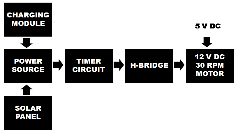
Block diagram
Component Description
Battery
We have used 12 volt lead acid battery here for back up.
Transformer
It consists of two coils of insulated copper wire linked by an iron core. Transformers are used to step up (increase) or step down (decrease) AC voltages. Energy is transferred between the coils by the magnetic field in the core. There is no electrical connection between the coils. Here we have used a shell type step down transformer which step downs 230 volt AC to 12 volt AC. It can supply maximum 1 A current.
Solar Panel
We have used here 12 volt solar panel to charge the battery. A solar cell (also called a photovoltaic cell) is an electrical device that converts the energy of light directly into electricity by the photovoltaic effect. It is a form of photoelectric cell, defined as a device whose electrical characteristics e.g. current, voltage, or resistance vary when exposed to light. Cells can be described as photovoltaic even when the light source is not necessarily the sunlight. Photons in sunlight hit the solar panel and are absorbed by semiconducting materials, such as silicon or germanium. Electrons are excited from their current molecular/atomic orbital. Once excited an electron can either dissipate the energy as heat and return to its orbital or travel through the cell until it reaches an electrode. Current flows through the material to cancel the potential and this electricity is captured for our use.
Capacitor
A capacitor stores electric charge. Capacitors used here are mica and electrolytic type.
Resistor
A resistor restricts the flow of current. The resistors used here are carbon film and quarter watt type.
Transistor
A transistor amplifies current. It can be used with other components to make an amplifier or switching circuit. BC 547 is a general purpose transistor. It is an npn epitaxial silicon transistor. Its maximum collector current (DC) is 100mA.
LED (Light Emitting Diode)
It is a transducer which converts electrical energy into light energy.
Motor
A motor is a device which converts electrical power into mechanical power. Here we have used a 12 volt permanent magnet type DC motor. It is a gear type motor with high torque and low rpm.
Diode 1N4007
These are general purpose diodes. These diodes have high current capability and low forward voltage drop. The average rectified output current is one ampere.
NE 555
The 8-pin NE 555 timer is the most useful ICs ever made in the world. Its popular name is timer IC. It is used in many electronics projects. Just adding a few external components, it can be used to construct so many circuits. The 555 has three operating modes: Monostable mode, Astable mode and Bistable mode. It can withstand maximum supply voltage up to 16 volt. It has a maximum power dissipation up to 600mW.
7805 voltage regulator
The 7805 voltage regulator IC gives us a constant 5 volt DC power supply from a 12 volt rectified output voltage. So , where the rest of the 7 volt goes ? Actually, the rest 7 volt goes nowhere. It is dissipated as heat in the heat sink provided to the voltage regulator IC.
Relay
Generally relay is defined as an electromagnetic switch. The relay used here is a 12 volt ice cube type.
Working
The horizontal strong and light weight bridge is mounted on the vertical shaft of motor. Before arrival of the train, the rotating solid bridge structure connects the rail track. The audio and visual signal system warns the vehicles. After departure of the train, the bridge returns back to its previous position where it connects the road. The rectifier circuit feeds
12 volt to the project.

The full bridge rectifier converts 12 V AC into 12 V DC and filtered by the 1000 µF capacitor. The LED in series with 1 kΩ resistor is just for power indication purpose. The output is connected to 12 V battery terminals for charging. A diode is connected in series with the positive output of rectifier circuit and positive terminal of 12 V battery to avoid continuous glowing of power indicator even when we are not charging.
Advantage
- This bridge is safe for both public and good transport.
- This system is pollution less.
- This process is cost reducing and environment friendly.
Contact:
Er. Anil Kumar Prusty
Phone no. +91 9861004895
Related Posts

Electrified High Way For Electric Car.
Introduction Resonant power transmission is a very special and widely…

Protection of school students and school bus from alcohol.
Introduction: By taking the help of modern engineering and technology,…

Sign Language To Text Conversion
Introduction: By using five flex sensors and microcontroller we have…