Introduction
In this project we are making a speed control system in which the speed of a DC motor is controlled by varying a potentiometer. This is a very simple and exciting approach towards speed control technology by changing the armature voltage. In this modern technical era there is no doubt that most works are performed by different machines. A motor is a dominant part in a machine. To operate a machine in a desired and safe condition a speed control provision is essential. In this project we are operating a small dc shunt motor. Electrical speed control methods are always proved better than mechanical speed control mechanism. If there is no speed control provision and the supply voltage is fixed then a DC shunt motor is accepted as a constant speed motor. Here we will use some simple and easily available components to construct the speed control circuit.
Components required
Vero board
Red LED
Green LED
Resistors 1.5 k Ω, 1 kΩ, 270 Ω
Variable Resistor 10 kΩ
Capacitor
Diode 1N4007
12 V Battery
BO Motor
Transistors BC 547, BD 140
Transformer
Components Description
Resistor
A resistor restricts the flow of current. The resistors used here are carbon film and quarter watt type.
LED (Light Emitting Diode)
It is a transducer which converts electrical energy into light energy.
Capacitor
A capacitor stores electric charge. Capacitors 470 µF and 100 µF are electrolytic type.
Transistor
A transistor amplifies current. It can be used with other components to make an amplifier or switching circuit. BC 547 is a general purpose transistor. It is an npn epitaxial silicon transistor. Its maximum collector current (DC) is 100mA.
BD 140 is a pnp epitaxial silicon transistor produced by Fairchild Semiconductor. It is suitable for medium power linear and switching applications. Its maximum collector current (DC) is 1.5 A.
1N4007
These are general purpose diodes. These diodes have high current capability and low forward voltage drop. The average rectified output current is one ampere.
Transformer
It consists of two coils of insulated copper wire linked by an iron core. Transformers are used to step up (increase) or step down (decrease) AC voltages. Energy is transferred between the coils by the magnetic field in the core. There is no electrical connection between the coils. Here we have used a shell type step down transformer having a mid-point tapping which step downs 230 volt AC to 12 volt AC. It can supply maximum 1A current.
12 V Battery
We have used three number of 4 volt lead acid batteries in series to get 12 V. You can use directly a 12 V battery if available.
BO Motor
BO stands for Battery Operated. BO motors are suitable for electronics hobby activities especially for small projects. It consists of small DC motor with gear arrangement to increase the torque. It is used in many DIY Robotic applications that are operated through batteries.
Working
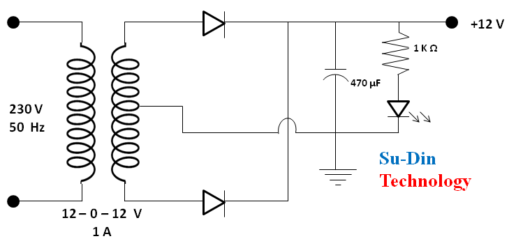
The speed control circuit operates through 12 V DC supply. The mid-point full bridge rectifier converts 12 V AC into 12 V DC and filtered by the 470 µF capacitor. The advantage of using a mid-point rectifier circuit is, we will get full wave rectification using only two diodes instead of four. The LED in series with 1 kΩ resistor is just for power indication purpose. The output is connected to 12 V battery terminals for charging. A diode is connected in series with the positive output of rectifier circuit and positive terminal of 12 V battery to avoid continuous glowing of power indicator even when we are not charging.

Here we have designed simple circuit based on two transistors that can be used to control the speed of a 12V DC motor. The left LED series with a resistance in the circuit diagram is just a power indicator. A 10kΩ variable resistor is used to control the speed of motor. This project runs on 12 volt DC. Here we have used a 12 volt rechargeable lead acid battery.
When the resistance value of the variable resistor decreases, it increases the base current of transistor BC 547 which in turn decreases the collector voltage of the same transistor. Since the collector of BC 547 is coupled to the base of transistor BD 140, the decrease in collector voltage of BC 547 forward biases BD 140 more and that’s why the speed of the motor increases. What actually happens here is the voltage across the armature of motor is controlled. There is an LED series with a resistance which is connected to collector of BD140. The brightness of the LED will be proportional to the speed of the motor. The 100 µF shunt capacitor across the motor acts like a voltage booster. In a DC motor, Speed of armature is directly proportional to back emf and inversely proportional to magnetic flux.
Mathematically,
N α Eb /ɸ
Where,
N = speed in rpm.
Eb = back emf
ɸ = field flux
As we are using a permanent magnet dc motor, here field flux is practically constant. So, now
N α Eb
But Eb = V – IaRa
Where,
V = voltage across the armature
Ia = armature current
Ra= armature resistance
Definitely Ra is fixed here, when Vvaries Eb also varies. Thus, when voltage across armature is variable, the back emf varies accordingly. As back emf is directly proportional to armature speed, a variable back emf will provide us a variable speed. This is how the speed is controlled.
Applications
This idea of speed control has a wide range of applications. Any where there is a need for controlling the speed of a 12 V DC motor, the circuit can be used without any difficulty keeping in mind that the motor should consume a current which mustn’t exceed 1.5 Ampere. It is suitable for robotics application, where there is a manual speed control provision. We can also control the speed of a DC motor fan. For a toy car speed control this is suitable
Precaution
Use a proper heat sink for the transistor BD140.
Related Posts

ସୋଲାର ପାୱାର୍ଡ କ୍ଲିନ୍ଡ ରେଲୱେ ପ୍ଲାଟଫର୍ମ
ଉପକ୍ରମ: ଏକ ବିକସିତ ଓ ସ୍ୱଛ ରେଲୱେ ପ୍ଲାଟଫର୍ମ ନିର୍ମାଣ କରିବା ଉକ୍ତ…

Music system for deaf.
Introduction In this project by using engineering and modern technology,…

ଇଲେକ୍ଟ୍ରିଫାଏଡ ହାଇ ୱେ
ଉପକ୍ରମ: ଆଧୁନିକ ବୈଷୟିକ ବିଜ୍ଞାନ ଏବଂ ପ୍ରଯୁକ୍ତି ବିଦ୍ୟାର ସାହାଯ୍ୟ ନେଇ ଏଠାରେ…