Introduction
Dear reader, in this attempt we are going to make a wall avoiding robot. The technology we use here is basically sending and receiving IR radiation but in a very creative and productive way. IR stands for Infrared. This is a very simple and exciting approach towards the robotics world in which we are going to prepare a three wheeler robot vehicle which will avoid any direct collision with the wall. Here we will use some simple and easily available components to construct the circuit. Due to the relay provided in the circuit it will support any type of DC motors you have available which are suitable for electronic projects. But here we have preferred BO motors. This is suitable only for indoor application. Because the sunlight affects the performance of infrared light emitting diodes.
The fundamental idea behind the project.
In every remote controlled circuit the most common thing is there is a sender (or transmitter ) and a receiver. The receiver should detect the signal of a particular frequency sent by the transmitter and should function accordingly. Generally the remote faces toward the receiver for proper co-ordination. But, here both the transmitter and receiver point towards one direction. The basic idea is to send infra red radiation through an IR-LED, and then receive the same infra red radiation by another IR-LED of the exactly same type. The infrared radiation is received by reflection phenomenon by an obstacle just for example a wall.
Light Emitting Diodes (LEDs) exhibit an electrical property that they develop a negligible amount of potential difference across their terminals when they are exposed to light. Just like a photo-cell, but the output current is negligible. That means the voltage generated by the LEDs can’t be used to generate a reasonable amount of electrical power from light, It can only be detected. After that the op-amp plays a great role to make the process useful and functional.
Components Required
- LM 358 (Operational amplifier)
- Resistors 1 kΩ, 4.8 kΩ,
- Variable Resistor 10 kΩ
- capacitor
- Relay (5 volt)
- BC 547 (Transistor)
- IR LED (1 pair)
- Red LED
- Battery
- Transformer
- Diode 1N4007
- BO motor
- 7805 voltage regulator
- Vero board
Components Description
LM 358
The op-amp used here is LM358 which is a general purpose op-amp and easily available in market. It is a dual low power operational amplifier. It can operate with a supply voltage from 3V to 32 V.
Relay
Generally relay is defined as an electromagnetic switch. The relay used here is a 5 volt ice cube type.
Resistor
A resistor restricts the flow of current. The resistors used here are carbon film and quarter watt type.
Capacitor
A capacitor stores electric charge. Capacitor used here is 2200 µF and it is an electrolytic type.
LED (Light Emitting Diode)
It is a transducer which converts electrical energy into light energy.
IR LED
Infrared radiation is an electromagnetic radiation. It is a Longer wavelength radiation and can travel a comparatively longer distance. Actually infrared radiation is not visible to naked eye. Humans can see the light emitted by infrared light Emitting diodes (IR LEDs) by using a digital camera for example a mobile phone camera. These have wavelength which is longer than those of visible light. The wavelength of the infrared radiation is in between 700 nm to 1 mm. Most of the thermal radiation emitted by objects near room temperature is infrared.
Transistor
A transistor amplifies current. It can be used with other components to make an amplifier or switching circuit. BC 547 is a general purpose transistor. It is an npn epitaxial silicon transistor. Its maximum collector current (DC) is 100mA.
BO Motor
BO stands for Battery Operated . BO motors are suitable for electronics hobby activities especially for small projects. It consists of small DC motor with gear arrangement to increase the torque. It is used in many DIY Robotic applications that are operated through batteries.
Diode 1N4007
These are general purpose diodes. These diodes have high current capability and low forward voltage drop. The average rectified output current is one ampere.
7805 voltage regulator
The 7805 voltage regulator IC gives us a constant 5 volt DC power supply from a 12 volt rectified output voltage. So, where the rest of the 7 volt goes ? Actually, the rest 7 volt goes nowhere. It is dissipated as heat in the heat sink provided to the voltage regulator IC.
Transformer
It consists of two coils of insulated copper wire linked by an iron core. Transformers are used to step up (increase) or step down (decrease) AC voltages. Energy is transferred between the coils by the magnetic field in the core. There is no electrical connection between the coils. Here we have used a shell type step down transformer which step downs 230 volt AC to 12 volt AC. It can supply maximum 750 mA current.
Working of the circuit.
Here we have used two 4 volt rechargeable lead acid batteries. One is used to power the two motors and the other is used to power the circuit. The 5 volt relay works perfectly with the 4 volt battery without any disturbance. But the voltage shouldn’t be less than 4 V DC, otherwise the relay will be inactive. You can use three AA size batteries in series to get 4.5 volt supply if you have no intension to make the charging circuit. But you have to spend comparatively more money for that. We always prefer rechargeable batteries. Use a 3*2 vero board to fix the components properly. Here we are giving a 5 volt dc charging circuit using a voltage regulator IC and bridge rectifier. It is suitable to charge the 4 volt battery. Use a heat sink for the 7805 voltage regulator IC.

The sender circuit is very funny and still effective. The sender circuit is just an IR-LED in series with a 1kΩ resistor and powered by 4 volt battery. The receiver circuit is very simple and effective, there are two 1 kΩ resistors forming a voltage divider which provides 4V at the anode of the IR-LED (this is the sensor in the receiver circuit).
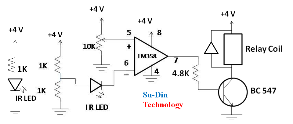
When IR light incidents on the IR-LED by reflection from any obstacle the voltage drop increases, the cathode’s voltage of IR-LED may drop as low as 1.4 V or more, depending on the light intensity. This voltage drop can be detected using an Op-Amp (operational Amplifier LM358). You have to adjust the 10 kΩ variable resistor so the voltage at the positive input of the Op-Amp (pin No. 5) would be somewhere near 1.6 volt. The output will be high when the voltage at the cathode of IR-LED drops under 1.6 volt. So the output will be high when IR light is detected. The output of the Op-Amp is fed to a relay driver circuit to operate the motors. The relay driver circuit consists of an npn transistor and a 4.8 kΩ resistor. This is how the receiver works.

One motor is fitted with left wheel and the other is with right wheel. The positive terminal of battery is connected to common pin of relay and one terminal of motor is connected to NC (normally connected) pin of relay. That means robot will march forward until it gets an obstacle. After facing the obstacle op-amp output becomes high, relay operates and motor stops. Mind the polarities of the two motors while connecting. That means the robot should move forward when the two motors rotate simultaneously.
How an op-amp works
An operational amplifier is an integrated circuit. Its primary work is to amplify weak electric signals. An operational amplifier consists of two input pins and one output pin. Its basic role is to amplify and output the voltage difference between the two input pins. The op-amp has 2 input, the +ve input, and the -ve input. If the +ve input’s voltage is higher than the -ve input’s voltage, the output will be high. Even an op-amp can detect a voltage difference of 0.0001 volts.
Application
If you want to add a safety feature for your robot that it should not damage by colliding with wall while moving in a workshop this idea is most suitable. It is very simple and contains no microcontroller chip.
Watch the video in our You Tube channel…
Related Posts

Controlling two servo motors simultaneously.
Introduction Servos or servo motors are used in electronics applications…

434 MHz RF transmitter and receiver circuit without microcontroller
Introduction Making your own radio frequency transmitter and receiver circuit…