21 April, 2023
0 Comments
1 category
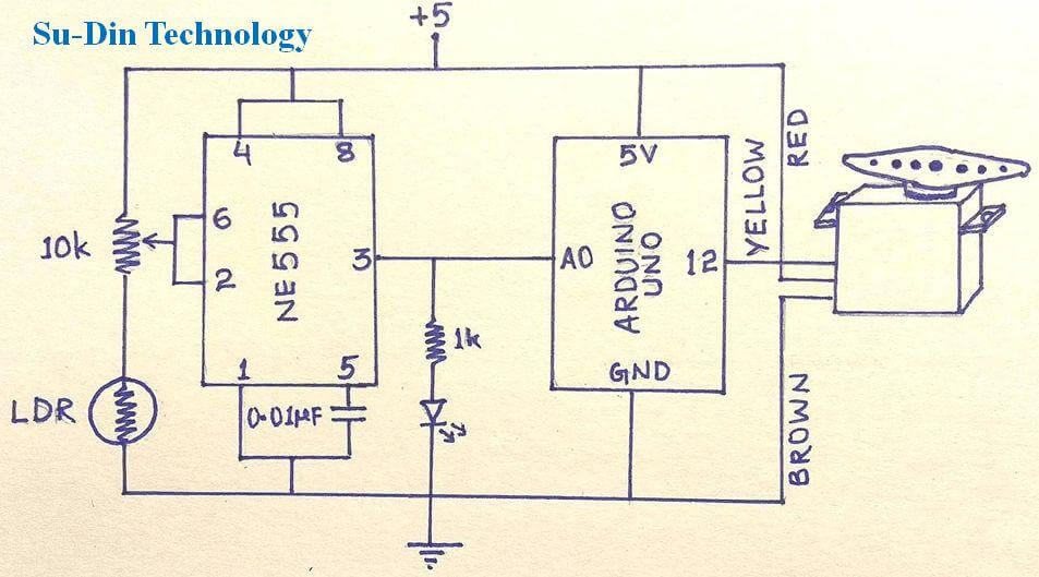
Circuit diagram of the project
Arduino Code
//Su-Din Technology  "sun tracking of solar panel"
#include<Servo.h>
Servo s1;
int readPin=A0;
int readVal;
float V=0;

int pos;
void setup() {
  pinMode(readPin,INPUT);
  Serial.begin(9600);
  s1.attach(12);//Control wire of servo to digital pin 12
  s1.write(pos=0); /*when project is initially powered,
           servo angle=0, to set it  towards EAST.
          THIS IS A RESET OF PROJECT*/
}
void loop()
{
readVal=analogRead(readPin);/*We have to read the analog voltage value at pin A0
                             whic is developed at pin 3 of 555 ic when light falls on LDR*/
V=(5./1023.)*readVal;
Serial.print(V);
Serial.println("volts");
delay(500);

if(V>3.0)/* I have used a dark activated circuit,
             In my case when torch light falls on LDR
             the voltage at pin 3 of 555 ic is  3.61*/
{
 pos = pos+5;  /*For each torch light on LDR,
               servo rotates 5 degree towards WEST*/
 s1.write(pos);
 delay(100);
 }
if(pos==180) /*This loop is to send back the shaft of servo again towards EAST
              after it has reached WEST*/
{
  delay(1500);
  s1.write(pos=160);
  delay(500);
  s1.write(pos=140);
  delay(500);
  s1.write(pos=120);
  delay(500);
  s1.write(pos=100);
  delay(500);
  s1.write(pos=80);
  delay(500);
  s1.write(pos=60);
  delay(500);
  s1.write(pos=40);
  delay(500);
  s1.write(pos=20);
  delay(500);
  s1.write(pos=0);
  delay(500);
  }
 delay(500);
}
Category: Uncategorized
Related Posts


Advanced eye friendly and eco friendly table lamp.
Introduction As human eyes are very precious organs, special care…
