Introduction
By taking the help of modern engineering and technology, in this project we are trying to reduce the travelling time period of an ambulance. If an ambulance is stuck in a traffic jam while carrying a serious patient to a hospital, then the ambulance has a control over the traffic signal. The ambulance can make its route clear by changing the red signal into green signal itself.
Components required
RF transmitter and receiver
Battery
Relay
Resistor
Diode
Capacitor
Transformer
LED
IC 4017
7805 voltage regulator
Transistor bc547
switch
Block Diagram

Components Description
RF transmitter and receiver
This is an PLL based ASK Hybrid 434 MHz RF transmitter and receiver module. It is ideal for short-range wireless control applications where quality is a primary concern. The transmitter module uses a SAW-stabilized oscillator, ensuring accurate frequency control for best range performance. The transmitter power supply ranges from a 3-12V, making it ideal for battery-powered applications. Here we will supply 5 volt. The receiver module requires no external RF components except for an antenna. The super-regenerative design exhibits exceptional sensitivity at a very cheap cost.
Relay
Generally relay is defined as an electromagnetic switch. The relay used here is a 12 volt ice cube type.
Resistor
A resistor restricts the flow of current. The resistors used here are carbon film and quarter watt type.
Diode 1N4007
These are general purpose diodes. These diodes have high current capability and low forward voltage drop. The average rectified output current is one ampere.
Capacitor
A capacitor stores electric charge. Capacitors used here are electrolytic and mica type.
Transformer
It consists of two coils of insulated copper wire linked by an iron core. Transformers are used to step up (increase) or step down (decrease) AC voltages. Energy is transferred between the coils by the magnetic field in the core. There is no electrical connection between the coils. Here we have used a shell type step down transformer which step downs 230 volt AC to 12 volt AC. It can supply maximum 1A current.
LED (Light Emitting Diode)
It is a transducer which converts electrical energy into light energy.
4017 IC
Here we are using a decade counter IC 4017, which counts or shifts the output for each rising edge of applied clock signal. It has 10 outputs.
7805 voltage regulator
The 7805 voltage regulator IC gives us a constant 5 volt DC power supply from a 12 volt rectified output voltage. So, where the rest of the 7 volt goes ? Actually, the rest 7 volt goes nowhere. It is dissipated as heat in the heat sink provided to the voltage regulator IC.
Transistor bc547
A transistor amplifies current. It can be used with other components to make an amplifier or switching circuit. BC 547 is a general purpose transistor. It is an npn epitaxial silicon transistor. Its maximum collector current (DC) is 100mA.
Working
The RF transmitter circuit is placed in the ambulance. The ambulance driver has control on the RF transmitter. The RF receiver along with its power supply circuit, latch circuit and relay outputs are placed near the traffic post. While carrying a serious patient if there is a red signal and the ambulance is facing a huge traffic, then the ambulance driver changes the red signal into green signal with the help of RF transmitter to make its route clear. Simultaneously the other three respective signals are turned into red to avoid any type of accidents. This above process is effective doesn’t matter from which direction the ambulance is proceeding at a traffic post.
First make the power supply circuit

Make the transmitter circuit which we have to install it in the ambulance. The ambulance driver will operate the circuit. It works with 434 MHz frequency.
Make the receiver circuit by following the diagram given below. This circuit is installed in the traffic post control panel. It works with 434 MHz frequency.

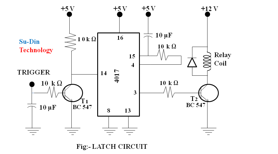
Prepare the latch circuit to control the light bulbs for traffic signals. Get the connections from the relay out puts. You have to make four latch circuits. The diagram is given below.
Advantages
This project reduces travelling time period of an ambulance.
It saves the life of a serious patient by carrying it to the hospital without facing any delay at a traffic post.
ENJOY THE MAKING PROCESS
Related Posts

କୁଲିଂ ହ୍ୟାଟ୍
ସର୍କିଟ୍ ଡାଇଗ୍ରାମ୍ ମୋଟର ବେଗ ନିୟନ୍ତ୍ରଣ ସର୍କିଟ୍ ଡାଇଗ୍ରାମ୍ Designer:Er. Anil Kumar…
ସେଫ୍ ଟ୍ରାନ୍ସପୋର୍ଟେସନ୍ ରୁଟ ଫର୍ ଇଣ୍ଡିଆନ୍ ଆର୍ମି
Designer:Er. Anil Kumar PrustyPhone No. :- 9861004895
