Introduction
In this project we are making a single phase inverter in which output will be 230 volt AC by taking the input as 12 volt DC. It is a simple square wave type inverter. It is the first step approach towards the inverter technology. The primary elements are two power transistors. We will learn to make an oscillator circuit by using those transistors with some biasing resistors. Here we will use some simple and easily available components to construct the inverter circuit.
Components required
Vero board
Red LED
Resistors 100 Ω, 15 Ω, 1 kΩ
Capacitor
Diode 1N4007
12 V Battery
Transistors
Transformer
Components Description
Resistor
A resistor restricts the flow of current. The 1 kΩ resistor used here is carbon film and quarter watt type. Rest are wire wound with power rating 10 watt.
LED (Light Emitting Diode)
It is a transducer which converts electrical energy into light energy.
Capacitor
A capacitor stores electric charge. Capacitor 470 µF is electrolytic type.
Transistor 2N3055
A transistor amplifies current. It can be used with other components to make an amplifier or switching circuit. A transistor amplifies current. It can be used with other components to make an amplifier or switching circuit. 2N3055 is a npn type complementary silicon power transistor. Its continuous maximum collector current rating is 15 ampere. It can withstand a maximum collector-emitter voltage of 60 volt. It is widely used in power applications. Here a proper heat sink is required, fitted tightly with the metal body of transistor.
1N4007
These are general purpose diodes. These diodes have high current capability and low forward voltage drop. The average rectified output current is one ampere.
Transformer
It consists of two coils of insulated copper wire linked by an iron core. Transformers are used to step up (increase) or step down (decrease) AC voltages. Energy is transferred between the coils by the magnetic field in the core. There is no electrical connection between the coils. Here we have used a shell type step down transformer having a mid-point tapping which step downs 230 volt AC to 12 volt AC. It can supply maximum 500mA current. The other transformer is used as a step up transformer which get 12 volt AC from inverter circuit and makes it 230 volt having current rating 2 ampere. You can use a higher current rating to get more wattage.
12 V Battery
We have used three number of 4 volt lead acid batteries in series to get 12 volt and have taken two sets of it to get more ampere. You can use directly a 12 volt battery if available.
Working
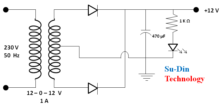
The inverter input is 12 volt DC supply. The mid-point full bridge rectifier converts 12 volt AC into 12 volt DC and filtered by the 470 µF capacitor. The advantage of using a mid-point rectifier circuit is, we will get full wave rectification using only two diodes instead of four. The LED in series with 1 kΩ resistor is just for power indication purpose. The output is connected to 12 volt battery terminals for charging. A diode is connected in series with the positive output of rectifier circuit and positive terminal of 12 volt battery to avoid continuous glowing of power indicator even when we are not charging.
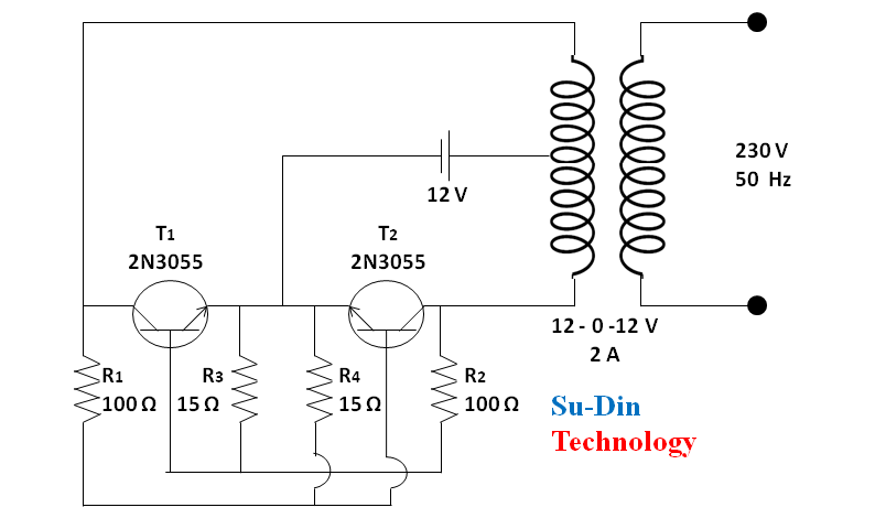
In place of 100 Ω resistor we have used two 47 Ω resistors in series and it gives 94 Ω which is close to 100 Ω. This is how in the practical world the selecting of components varies according to availability in the market in that particular instant. The transistor we have used here comes with metal body. The metal body itself is collector of the transistor. You may find difficulty in getting connection from the collector terminal by applying soldering iron. So, it will be a better option to use 1/8 size nut, bolt, washer with single core hard type copper wire. It is a saturable-core oscillator. There is no special separate feedback windings. The feedback is generated due to cross coupled connection just like in a multivibrator. It can be observed from the circuit diagram that to avoid unsymmetrical square wave production, unequal power dissipation and other malfunctions the biasing networks of the two same type transistors are balanced. The functioning of this inverter circuit is unique and different from the normal inverters which involve discrete oscillator stage for powering the transistors. It doesn’t matter the degree of matching of two halves of the circuit but practically there will be always a slight imbalance in the parameters surrounding them just like the resistors and transformer winding turns etc. Due to this reason, both the halves are not able to conduct simultaneously. Let’s assume that the transistor T1 conducts first. So it will get the biasing voltage through the lower half winding of the transformer via R2. After saturation and full conduction, the entire battery voltage is pulled through its collector to the ground. This sucks out dry any voltage through R2 to the base and it immediately stops conducting. This gives an opportunity for the transistor T2 to conduct and the cycle repeats in this way. The base Emitter resistors are used to fix a particular threshold for their conduction to break, they help to fix a base biasing reference level. The whole circuit starts to produce square wave oscillation. This 12 volt alternating quantity available at primary winding of transformer is stepped up to 230 volt AC.
Applications
This idea of making a simple inverter has a wide range of applications. Any where there is a need for AC we can use it with a 12 V DC battery just like to power small electrical appliances like soldering iron, CFL bulbs, small portable fans etc. The more will be the ampere hour of the battery, more the output wattage you will achieve but there is a specification limit of the circuit. It is easily affordable also. It is most suitable for science exhibition model.
Precaution
Use a proper heat sink for the transistors 2N3055.
Related Posts

ଇଲେକ୍ଟ୍ରିଫାଏଡ ହାଇ ୱେ
ଉପକ୍ରମ: ଆଧୁନିକ ବୈଷୟିକ ବିଜ୍ଞାନ ଏବଂ ପ୍ରଯୁକ୍ତି ବିଦ୍ୟାର ସାହାଯ୍ୟ ନେଇ ଏଠାରେ…

ହାଇପରଲୁପ ପରିବହନ ବ୍ୟବସ୍ଥା
ଉପକ୍ରମ: ହାଇପରଲୁପ ହେଉଛି ପରିବହନ ବ୍ୟବସ୍ଥାର ଏକ ନୂତନ ସଂକଳ୍ପନା । ଉଡାଜାହାଜ, …

ଜିରୋ ଓପନ୍ ଡିଫିକେସନ୍
ଉପକ୍ରମ ଉକ୍ତ ପ୍ରକଳ୍ପରେ ଶୌଚାଳୟର ବ୍ୟବହାର କରାଯାଇ ଜୈବ ଗ୍ୟାସ୍ ଉତ୍ପାଦନ ପ୍ରତି…