Introduction
In this project we are making a reciprocating cutting machine. This is a very simple and exciting approach towards reciprocating technology. In this modern technical era there is no doubt that most works are performed by different machines to reduce human effort. A motor is a dominant part in a machine in which electrical energy is converted into mechanical energy. To operate the cutter in a desired and safe speed we have also introduced a provision for speed controller. In this project we are operating a small permanent magnet dc shunt motor. Here we will use some simple and easily available components to construct the mechanism.
Components required
Vero board
Red LED
Resistors 1.5 k Ω, 1 kΩ, 270 Ω
Variable Resistor 10 kΩ
Crocodile clip
8 V Battery
Solar panel
BO Motor
Transistors BC 547, BD 140
Components Description
Resistor
A resistor restricts the flow of current. The resistors used here are carbon film and quarter watt type.
LED (Light Emitting Diode)
It is a transducer which converts electrical energy into light energy.
Transistor
A transistor amplifies current. It can be used with other components to make an amplifier or switching circuit. BC 547 is a general purpose transistor. It is an npn epitaxial silicon transistor. Its maximum collector current (DC) is 100mA.
BD 140 is a pnp epitaxial silicon transistor produced by Fairchild Semiconductor. It is suitable for medium power linear and switching applications. Its maximum collector current (DC) is 1.5 A.
8 V Battery
We have used two rechargeable 4 volt lead acid batteries in series to get 8 V.
Solar cell
A solar cell (also called a photovoltaic cell) is an electrical device that converts the energy of light directly into electricity by the photovoltaic effect. It is a form of photoelectric cell, defined as a device whose electrical characteristics e.g. current, voltage, or resistance vary when exposed to light. Cells can be described as photovoltaic even when the light source is not necessarily the sunlight. Photons in sunlight hit the solar panel and are absorbed by semiconducting materials, such as silicon or germanium. Electrons are excited from their current molecular/atomic orbital. Once excited an electron can either dissipate the energy as heat and return to its orbital or travel through the cell until it reaches an electrode. Current flows through the material to cancel the potential and this electricity is captured for our use.
BO Motor
BO stands for Battery Operated. BO motors are suitable for electronics hobby activities especially for small projects. It consists of small DC motor with gear arrangement to increase the torque. It is used in many DIY Robotic applications that are operated through batteries.
Working
By using reciprocating mechanism rotational motion can be converted into linear motion or to and fro motion or linear oscillator motion. Most of the useful works can be done by using reciprocating mechanism example cutting, punching, hammering etc. The main parts of this reciprocating mechanism are two bars and a circular disc. The centre of the disk aligns with shaft of motor. One end of the first bar is connected to the disc somewhere nearer to its perimeter. This selection of joining point defines your distance of blade movement. More the position towards periphery, more the movement of blade. Closer the position towards centre, less will be the movement of blade distance. Another end of first bar is attached to one terminal of second bar. Another terminal of second bar is connected to hacksaw blade. The blade joint should be strong enough and easy to reopen and reclose. We have used 1/8 size nuts and bolts for the joints. Lubrication of joints should be done properly. The second bar should be guided through aluminium guider for distortion free movement.
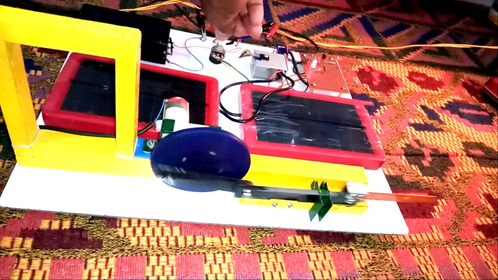
The speed control circuit operates through 8 V DC supply. The battery is charged by solar panel. Output of solar panel is 11 volt because we have used two panels in series each of 5.5 volt. 11 volt is enough to charge the 8 volt battery because charging current flows when there is a potential difference. The circuit functions well directly with solar cell as well.
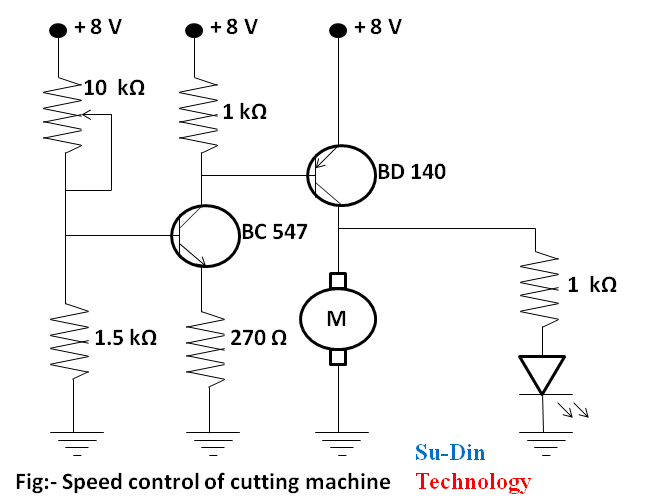
Here we have designed simple circuit based on two transistors that can be used to control the speed of a DC motor. A 10kΩ variable resistor is used to control the speed of motor.
When the resistance value of the variable resistor decreases, it increases the base current of transistor BC 547 which in turn decreases the collector voltage of the same transistor. Since the collector of BC 547 is coupled to the base of transistor BD 140, the decrease in collector voltage of BC 547 forward biases BD 140 more and that’s why the speed of the motor increases. What actually happens here is the voltage across the armature of motor is controlled. There is an LED series with a resistance which is connected to collector of BD140. The brightness of the LED will be proportional to the speed of the motor. You can connect a 100 µF shunt capacitor across the motor to enhance its performance. In a DC motor, Speed of armature is directly proportional to back emf and inversely proportional to magnetic flux.
Mathematically,
N α Eb/ɸ
Where,
N = speed in rpm.
Eb = back emf
ɸ = field flux
As we are using a permanent magnet dc motor, here field flux is practically constant. So, now
N α Eb
But Eb = V – IaRa
Where,
V = voltage across the armature
Ia = armature current
Ra= armature resistance
Definitely Ra is fixed here, when Vvaries Eb also varies. Thus, when voltage across armature is variable, the back emf varies accordingly. As back emf is directly proportional to armature speed, a variable back emf will provide us a variable speed. This is how the speed is controlled.
Applications
The idea can be implemented to cut wood, pvc pipes, metal pipes etc. It is best suitable for carpentry work. The main important feature in it is, cutting process can be adjusted to your desired angel and plane.
Precaution
Use a proper heat sink for the transistor BD140.
Enjoy the making process in our YouTube channel…
Related Posts


SPEED CONTROL OF DC MOTOR BY FOUR QUADRANT CHOPPER.
Introduction The project is designed to develop a four quadrant…

Foot Dust Cleaning Machine
Introduction Foot Dust Cleaning Machine is especially useful in medical…