Introduction:
By taking the help of modern engineering and technology, here we have designed a safe transportation route for Indian army. It is going to help our solders by not allowing the suspected vehicles to army areas. By stopping the introducers and attackers before time, we can save the lives of our solders.
Block diagram:

Components required:
- Servo motor
- NE 555 IC
- Microcontroller
- LED
- LDR
- LASER
- Buzzer
Working:
The entry road to army area is guarded by an invisible laser beam. This beam is sent from one side of road and continuously made to fall on a sensor situated at the other side of road. When this beam is crossed by any introducer, a signal is sent to microcontroller. As a result servo motor rotates from 0 to 90 degree. In this way the check gate is closed automatically to stop the vehicle. Consequently a danger signal and an alarm is activated at the control chamber. Now, only the solder at the control chamber can open the gate by pressing the switch. If the solders consider the vehicle safe after investigation, then this vehicle can be allowed. Otherwise if they found it suspected, strong action is taken by the solders against the suspected vehicle. This process eradicates further disturbance and saves the lives of our solders.

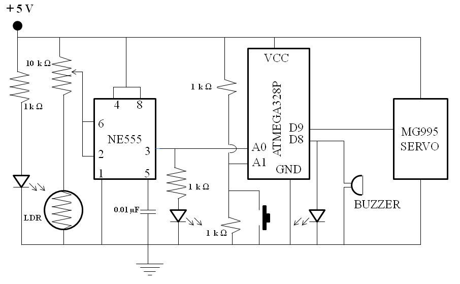
Circuit diagram:
Advantages:
- It is an automatic process.
- This arrangement avoids the attacker, introducer and enemy vehicles.
- The lives of our solders can be saved and situations like Pulwama attack can be avoided.
Code for Microcontroller:
//Su-Din Technology  "Safe transportation route for army"
//CONTROL SIGNAL WIRE OF SERVO MUST BE ATTACHED TO A PWM PIN OF ARDUINO
#include<Servo.h>
#define buzzer 8
Servo s1;
int readPin0=A0;
int readPin1=A1;
int readVal0;
int readVal1;
float V1=0;
float V2=0;

void setup() {
  pinMode(readPin0,INPUT);
  pinMode(readPin1,INPUT);
  pinMode(buzzer,OUTPUT);
  Serial.begin(9600);
  s1.attach(9);//Control wire of servo to PWM pin 9
  s1.write(0); /*when project is initially powered,
           servo angle=0, to set the gate at open position.
          THIS IS A RESET OF PROJECT*/
}
void loop()
{
readVal0=analogRead(readPin0);/*We have to read the analog voltage value at pin A0
                                                       which is developed at pin 3 of 555 ic when light falls on LDR*/
V1=(5./1023.)*readVal0;
Serial.print(V1);
Serial.println("volts");
delay(500);

readVal1=analogRead(readPin1) ;
V2=(5./1023.)*readVal1;  /*This is the voltage value at the voltage
                                           divider circuit which is set at 2.5 V */

Serial.print(V2);
Serial.println("volts");
delay(500);


if(V1<3.0){
 s1.write(90);
 digitalWrite(buzzer, HIGH);
 delay(900);
 digitalWrite(buzzer, LOW);
 delay(500);
 digitalWrite(buzzer, HIGH);
 delay(900);
 digitalWrite(buzzer, LOW);
 delay(500);
 digitalWrite(buzzer, HIGH);
 delay(900);
 digitalWrite(buzzer, LOW);
 delay(2000);
        }

if(V2==0){ /*This loop is to send back the gate open*/
  s1.write(0);
          }
delay(1000);
}
Related Posts


ସୋଲାର ପାୱାର୍ଡ ସ୍ମାର୍ଟ ଡଷ୍ଟବିନ
ଉପକ୍ରମ: ଆମ କାର୍ଯ୍ୟକ୍ଷେତ୍ରର ଚତୁଃପାର୍ଶ୍ୱ କୁ ନିର୍ମଳ ରଖିବା ପାଇଁ ଆମେ ଡଷ୍ଟବିନ…
