

Introduction
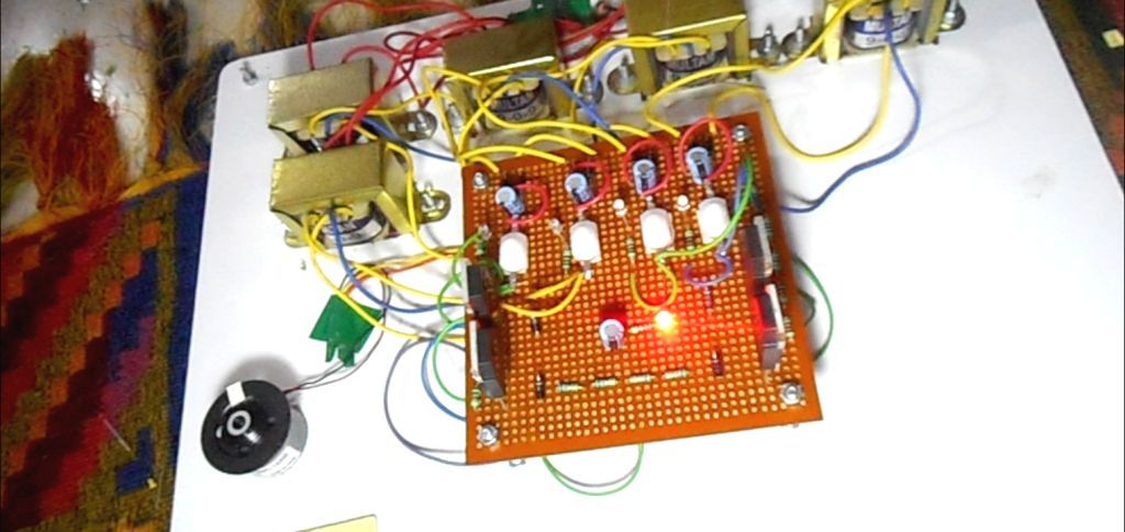
The project is designed to develop a four quadrant control system for a DC motor. The motor is operated in four quadrants i.e. clockwise; counter clock-wise, forward brake and reverse brake. The four quadrant operation of the dc motor is best suited for industries where motors are used and as per requirement as they can rotate in clockwise, counter-clockwise and also apply brakes immediately in both the directions. In case of a specific operation in industrial environment, the motor needs to be stopped immediately. In such scenario, this proposed system is very appropriate as forward brake and reverse brake are its integral features. This project can be enhanced by using higher power electronic devices to operate high capacity DC motors. Regenerative braking for optimizing the power consumption can also be incorporated.
Components required
Transformer
Motor
IGBT
Diodes
Capacitor
Resistors
LED
Components Description
Transformer
It consists of two coils of insulated copper wire linked by an iron core. Transformers are used to step up (increase) or step down (decrease) AC voltages. Energy is transferred between the coils by the magnetic field in the core. There is no electrical connection between the coils. Here we have used a shell type step down transformer which step downs 230 volt AC to 9 volt AC. It can supply maximum 500 mA current. We have used four transformers for driving four IGBTs independently through four bridge rectifiers.
Motor
A motor is a device which converts electrical power into mechanical power. Here we have used a small 6 volt permanent magnet type DC motor. As we have used 9 volt transformer and bridge rectifier so we get 9 volt DC. Use resistor to drop the voltage to 6 volt.
IGBT
The Insulated Gate Bipolar Transistor (IGBT) is a minority-carrier device with high input impedance and large bipolar current-carrying capability. Many designers view IGBT as a device with MOS input characteristics and bipolar output characteristic that is a voltage-controlled bipolar device. To make use of the advantages of both Power MOSFET and BJT, the IGBT has been introduced. It’s a functional integration of Power MOSFET and BJT devices in monolithic form. It combines the best attributes of both to achieve optimal device characteristics. The IGBT we have used here is a general purpose type. It can handle a voltage up to 1200 V and 25 A. Generally this is used in domestic induction cookers. You can go to any electronic component shop and ask for 25N120 IGBT. It is a NPT trench IGBT. You can use heat sink for heavier load but here for driving this 6V DC motor no heat sink required.
Capacitor
A capacitor stores electric charge. Capacitors used here are 100 µF and are electrolytic type. They function like filters.
Resistor
A resistor restricts the flow of current. The resistors used here are carbon film and quarter watt type.
Diode 1N4007
These are general purpose diodes. These diodes have high current capability and low forward voltage drop. The average rectified output current is one ampere.
LED (Light Emitting Diode)
It is a transducer which converts electrical energy into light energy. Here these are used for power indication purpose only.
Block diagram

Four Quadrant Operation of Motor: The motor will act as a motor for specific periods and will also act as a generator at other times . There are also instances in which the motor might act as a brake. There are several applications in which motor may be required to run in both the directions. Therefore, in sketching the speed torque characteristics of the motor or the load, it is preferable to make use of all the four quadrants of the speed torque plane for plotting rather than simply confining into first quadrant operation.
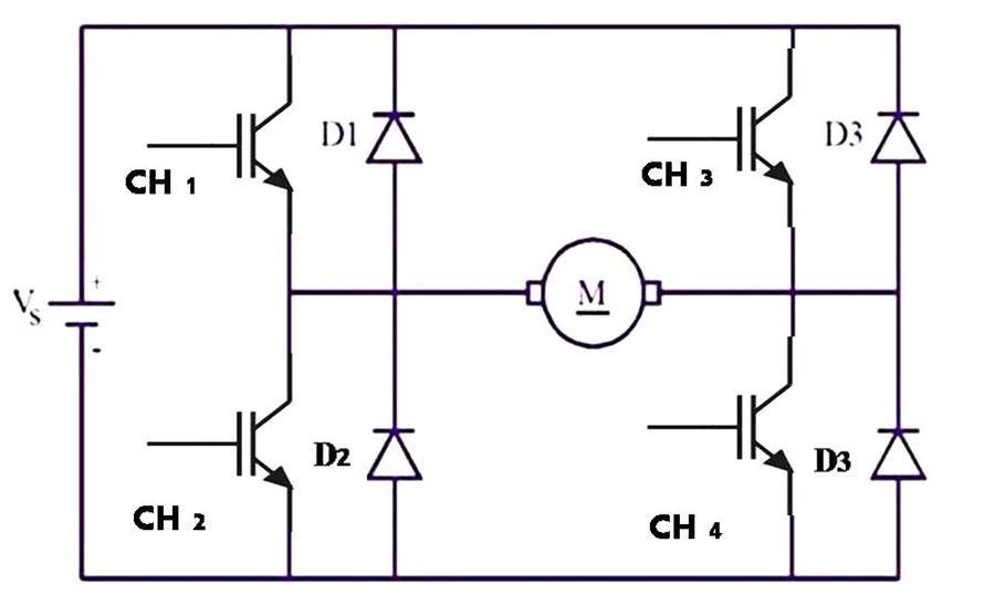
Conventions used in the study of the four quadrant chopper:
The speed is assumed to have a positive sign, if the direction of rotation is counter clockwise or is in such a way to cause an upward or forward motion of the drive. In case of reversible drives, the positive sign for speed may have to be assigned arbitrarily either to counter clockwise or clockwise for rotation. The motor torque is taken to be positive when it causes an increase in speed in the positive sense. The load torque is assigned a positive sign when it acts against the motor torque.
The field polarity is maintained and the armature current is reversed to obtain negative torque, the same effect is obtained by reversing the field polarity and maintaining the armature current direction. Field reversal is necessary with some forms of rectifier control. These four quadrants of operation are feasible for any DC or AC rotating machine but the DC machine is much freer to transfer its operation between quadrants and operates satisfactorily at any point within the envelope. The four modes of operation of a DC motor are discussed here under:
Forward Motoring Mode:
In the forward motoring mode of operation, armature current flows in opposition to the EMF induced in the armature. The direction of EMF induced in the armature is in direct opposition to the applied voltage. The torque developed is in the direction of armature rotation.
Regenerative Braking Mode:
In this mode the motor is made to operate as a generator and the kinetic energy of the motor and load coupled to it is converted in to electrical energy, part of which is returned to the supply and rest of the energy is lost as heat in the windings and bearings of electrical machines. The armature current and induced EMF in the motor is in the same direction but in opposition to supply voltage .The torque developed is in direction opposite to that of rotation of armature.
Reverse Motoring Mode:
In this mode the motor is made to operate as generator and the kinetic energy of the motor is converted into electrical energy. This electrical energy is dissipated in braking resistance connected to the terminals. When the chopper is turned on by a gate pulse, the kinetic energy is partly dissipated in armature resistance and partly stored in armature inductance. When chopper is turned off, the energy stored in inductance is transferred to braking resistance and dissipated as heat.
Reverse Generating Mode:
Reverse generating mode is feasible only if motor generated emf is made to exceed the dc source voltage.
Applications
The four quadrant operation of the dc motor is best suited for industries. It is useful for traction and locomotive.